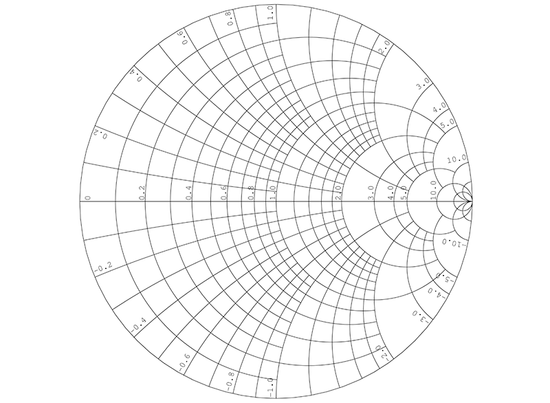

We first locate the normalized impedance z L 2 + j2 on the Smith chart (Figure 14). Part 1 looked at impedance matching and the need for a complex conjugate impedance at the load, compared to the source impedance. Impedance Matching and the Smith Chart: The Fundamentals Abstract: Tutorial on RF impedance matching using the Smith chart. Using an impedance Smith chart, design a matching network to transform Z L 100 + j100 to Z In 50. Impedance matching and the Smith Chart, Part 2. The purpose of this section is to use the Smith chart to present several design options for matching a source to a load, see Figure 6.9.1. The computational values are required to set up the type of structure and target component values.\)(a). Maxim > Design Support > Technical Documents > Tutorials > Wireless and RF > APP 742 e'ords smith chart RF impedance matching transmission line Related Parts. a short circuit, or a termination resistance equal to the characteristic impedance Z. 6.9.4 Design 1 with an Open-Circuited Stub. This method is also used to display the behavior of the RF parameter at one or more frequencies. It is a graphical calculator used for solving complex problems of transmission lines and matching circuits. With experience it will be found that this is the preferred approach to developing designs, as trade-offs can be captured graphically. In-situ RF lab measurements, along with tuning work, have to be considered for determining the proper final values. Smith Chart Impedance Matching The smith chart was invented by Philip H Smith and T. The lumped-element matching networks presented up to now can also be developed using Smith charts which provide a fairly intuitive approach to network design. We can locate z 1 in the immittance Smith chart and directly read from the orange curves its equivalent admittance. For example, assume that the normalized load impedance is z 1 1 + j1. Above a few tens of megahertz, theoretical calculations and simulations are often insufficient. With an immittance Smith chart, we can easily find the equivalent admittance of a given impedance or vice versa.


The matching task is required for a proper transfer of signal and energy from a "source" to a "load." At high radio frequencies, the spurious elements (like wire inductances, interlayer capacitances, and conductor resistances) have a significant yet unpredictable impact on the matching network. Typically these include the antenna to the low-noise amplifier ( LNA ), power-amplifier output (RFOUT) to the antenna, and LNA/VCO output to mixer inputs. This article will be dedicated to examples and questions to find out how much you really know about Smith chart and enhance your understanding of this great chart. One is the need to match the different impedances of the interconnected blocks. When dealing with the practical implementation of RF applications, there are always some nightmarish tasks.


 0 kommentar(er)
